Vaya más rápido en la dirección correcta.
Choose your language
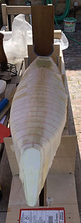
Coloca el casco

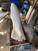
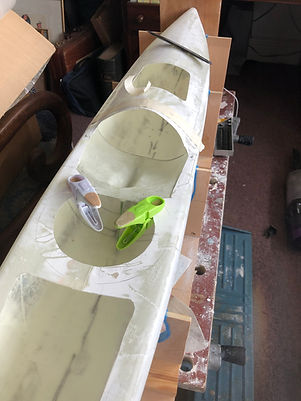
Con el tapón encerado estaba listo para construir un barco. El resultado final después de pintar con imprimación de alto espesor y mucho lijado se muestra en la foto. Este está listo para equipar.
Haga clic en cualquier imagen para ampliar la imagen.
Build the hull on the male mould
What you need
Glass cloth. 2*135gm E cloth and 1x124gm S cloth.
Slow cure epoxy East Coast fibreglass
2 pack high build epoxy primer. SML Paints
Roller
Paint brush
Mixing pots
Safety glasses
The process
Making the hull and components
My first question was what layup to use. Looking at the boat builder sites, I guessed my layup would provide a strong but not too heavy boat however I tried a few layups on a test mould to see what I would get. In the end I used 2*135gm E cloth and 1x124gm S cloth. I am going to build a new boat and use 3 layers of 124gm S cloth which is stronger and will use less epoxy.
At the same time as laying up the hull, I made the hull components using the same layup. I needed a mould for the deck area just aft of the foredeck. The picture shows the mould under construction prior to rubbing smooth.

Components for the bow, stern and bulkhead, simply a glass and epoxy sheet laid on a flat board covered in packaging tape which is a great release agent. For the rudder and servo supports, I laid glass over strip wood wrapped in packaging tape to create a light rigid beam to bond across the boat.

The hull is laid up in the same way as the plug. Pre cut the cloth and mark a centreline on the hull and the cloth. Allow for an overlap of 1 inch on the foredeck.

I used West systems slow cure epoxy resin which in the Summer gave me about half an hours work time. Stop work when the epoxy starts to go stringy and clean your tools with Acetone before mixing a fresh pot of epoxy.
I use Nitril gloves which I wash in acetone to remove any sticky epoxy. I also use a full face filter mask although this is not needed. Unlike Polyurethane, epoxy does not smell too bad
To begin the layup, paint the hull with epoxy.
Add the first layer of E cloth and saturate the glass with epoxy using the aluminium roller. Take your time and make sure you get rid of all air bubbles. I worked on the hull first and then turned the mould over to work on the deck. Allow a 1 inch overlap on the deck and cut any excess cloth away with scissors. Keep a jar of acetone handy to keep the scissors clean.
I added more epoxy over the first layer of E cloth prior to adding the second layer. Roll out and finish as per the first layer. Repeat for the final layer of S cloth
Wrap the finished hull tightly in Peel ply.
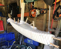
When I built the hull in about 75 degrees, I had to mix a second lot of epoxy for the final layer of S cloth as the first lot started curing.
Once hardened, remove the peel ply, then add 2 coats of high build epoxy primer. Like the plug the hull will look a mess but will look great once sanded.
Sand the hull so you can see through to glass but do not cut any fibres. This will make the hull as light as possible and ready for a top coat of 2 pack polythene which is done after fit out. Fix any faults/holes as necessary.
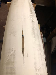
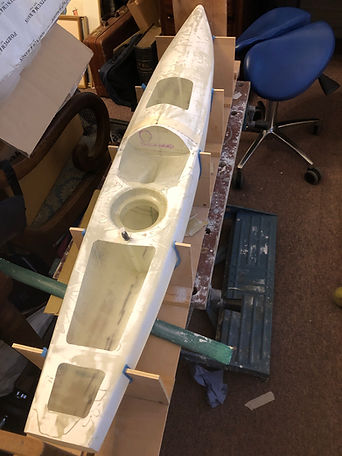
Once happy with hull finish cut through the centreline of the the foredeck and stern deck. Brad suggested a knife but I used a fine cutter on a Dremel. Prise the hull off the mould. This process was much easier than I thought it would be. The whole structure is flexible so once off the mould so put in a jig to keep the designed shape.


Termina la cubierta principal
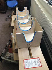
Tan pronto como el casco esté fuera del molde Consígalo directamente en una plantilla para sostener el casco. Recorté marcos de madera contrachapada usando los planos y los fijé en una tabla plana resistente. La plantilla se utilizará para alinear la aleta y el timón.
Haga clic en cualquier imagen para ampliar la imagen.
Bond the foredeck and stern deck

What you need
-
5 minute epoxy
-
Slow cure epoxy
-
Bent piece of wire as long as the foredeck
-
1" glass tape
-
Bow and stern plates
The process
Tape the the top of the previously cut foredeck and stern together with masking tape prior to bonding below.
Sand the underside of the foredeck to provide a key for the 1"tape you are about to apply
Bond the underneath of cut foredeck and stern deck with 1" fibreglass tape.

Allow to cure and remove the masking tape. I put the glass tape underneath the deck and on top but I think you only need to bond underneath and fill the gap on top.
To get the tape all the way up the foredeck, wet the tape with epoxy and roll up. Using the wire with a 1" bend at the end, to support the roll and unroll it right (with the hull upside down) to the end of the foredeck. Once unrolled it should sit flat and use the wire to move the tape if necessary. See image 4.
Remember to put some peel ply over the top of the tape on top of the deck. Image 6. (This was probably an unnecessary step as I think the tape only needs to go on the underside.)
The foredeck will be very strong because you will have 6 layers of glass including the overlay and the 1" tape. Slightly over engineered I think.
Repeat the process on the stern deck. I had to put a plate across the stern and the next bridge as I had not finished the original layup properly. Image 8 and 9.


Having taped on top of the foredeck I had to re apply 2 coats of high build epoxy and sand down. There is no need to do this if you bond underneath the deck only.
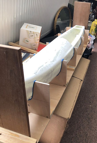
I fitted 2 perpendicular end plates onto the jig so I could shape the bow and stern on the hull to be, one, vertical and two, at 90 degrees to the centre line of the boat. Image 10

Trim the bow and stern plate and fit with 5 min epoxy. Spot glue in place initially and then seal and fillet with epoxy and micro balloons.
Une la cubierta de proa y la cubierta de popa
Que necesitas
Epoxi de 5 minutos
Epoxi de curado lento
Pedazo de alambre doblado tan largo como la cubierta de proa
Cinta de vidrio de 1 "
Placas de proa y popa
El proceso
Pegue con cinta adhesiva la parte superior de la cubierta de proa y la popa previamente cortadas con cinta adhesiva antes de unir la parte inferior. Ver imagen 5.
Lije la parte inferior de la cubierta de proa para proporcionar una llave para la cinta de 1 "que está a punto de aplicar.
Pegue la parte inferior de la cubierta de proa cortada y la cubierta de popa con cinta de fibra de vidrio de 1 ". Imagen 4. Deje curar y retire la cinta adhesiva. Pongo la cinta de vidrio debajo de la plataforma y encima, pero creo que solo necesitas unir debajo y llenar el espacio en la parte superior.
Para que la cinta llegue hasta la cubierta de proa, humedezca la cinta con epoxi y enróllela. Usando el cable con una curva de 1 "al final, puede sostener el rollo y desenrollarlo (con el casco al revés) hasta el final de la cubierta de proa. Una vez desenrollado, debe quedar plano y usar el cable para mover la cinta si es necesario. Ver imagen 4.
Recuerde poner un poco de peel ply sobre la parte superior de la cinta en la parte superior de la plataforma. Imagen 6. (Este fue probablemente un paso innecesario ya que creo que la cinta solo necesita ir en la parte inferior).
La cubierta de proa será muy fuerte porque tendrá 6 capas de vidrio, incluida la superposición y la cinta de 1 ". Un poco más de ingeniería.
Repita el proceso en la cubierta de popa. Tuve que poner una placa en la popa y el siguiente puente ya que no había terminado correctamente la bandeja original. Imagen 8 y 9.
Habiendo pegado con cinta en la parte superior de la cubierta de proa, tuve que volver a aplicar 2 capas de epoxi de alto espesor y lijar. No es necesario hacer esto si se une solo debajo de la plataforma.
Coloqué 2 placas de extremo perpendiculares en la plantilla para poder dar forma a la proa y la popa del casco para que estuvieran, una, vertical y dos, a 90 grados con respecto a la línea central del barco. Imagen 10
Recorte la placa de proa y popa y ajústela con epoxi de 5 min. Inicialmente, coloque el pegamento en su lugar y luego selle y filetee con epoxi y microglobos. La figura 8 muestra el ajuste inicial.
Finalmente, retire el exceso de plataforma para que los agujeros sean visibles de acuerdo con el plan. Ver imagen 7 y 8.
En la imagen 5, solo la cubierta de popa está en su lugar. En el próximo barco completaré la cubierta hasta el poste del enchufe.
Ahora viene lo que creo que es la parte más difícil del proceso de construcción. Calificación y hacer un agujero en el casco para la aleta y pegar en una caja de aleta alineada y unirla a la cubierta y al mamparo delantero. Cuando construya mi próximo barco, agregaré imágenes del posicionamiento de las aletas.
Haga clic en cualquier imagen para ampliar la imagen.
The fin case, bulkhead and forward aft deck
What you need
-
5 minute epoxy
-
Slow cure epoxy
-
Fin
-
Fin case
-
Rudder
-
Rudder stock brass tubes
-
Cross bars for rudder stock and rudder servo mount.
-
Prepared forward part of the aft deck
-
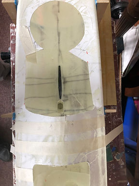
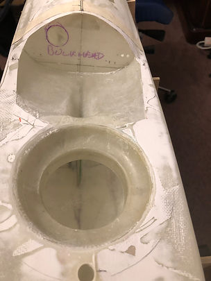
Cut out bulkhead shape to fit under fordeck
-
1"glass tape
-
Various fittings, jib tack bolts, mast ram, mainsheet post, back stay bolt, mainsheet pulley blocks, fairleads to allow the endless mainsheet to go through bulkhead
The Details
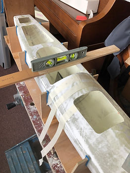
Tape the hull into the jig so the shroud points on the deck are parallel to the base of the jig. Everything will be aligned to this.
Measuring from the stern datum, mark the front and back of the fin hole on the outside of the hull. Then mark a centreline which you will have marked on the frames of the jig. This will get the correct alignment for the fin hole. Remove the hull and using the fin, mark the contour of the fin. Cut out the slot for the fin using a Dremel or similar being careful to cut well inside the line. Use sandpaper to open the slot to fit the fin exactly.
Tape the hull back in the jig. With the fin in the slot, push the fin case over the fin so that the bottom of the case is lying on the hull.
There are two measurements on the plan to align the fin, one shows the tip of the fin where is enters the bulb. This should be 330mm from the bottom of the hull and the other measures from the same fin tip to the bottom of the bow of the boat. If set up correctly the leading edge of the fin should be perpendicular to the waterline. Shape the bottom of the fin box and fin until this is achieved. Ideally the fin should fit all the way into the fin box.
I used some string to determined the position of the tip of the fin.

Reinforce the shroud bolt locations with half an inch of 1" tape and once dry fit the shrouds.
There is a huge amount of strength with this design in this area and no further reinforcement is needed.
Fit the shroud bolt now while you have access to the underside of the deck.
Once the base of the fin box is shaped and the fin aligned, now is the time to dry fit the forward part of the aft deck and trim the top of the fin box until the deck fits snuggly. Spot glue the fin box in place with the fin in the box and support in the right position.

Once fixed seal the fin box to the hull with 5 min epoxy and microballoons with a small fillet. Finally reinforce the fin box to the hull with 1"glass tape and epoxy.

With the fin box in place, dry fit the forward part of the deck with the fin box and forward bulkhead.
Once happy with fit, do a final check that the forward bulkhead is in the right place from the stern datum. Get this wrong and you will have issues with your mast ram. Spot glue with 5 min epoxy and micro balloon. With 5 min epoxy and micro balloon seal the bulkhead and seal where the fin box connects with the deck. Finally reinforce the top of the fin box with fin one inch tape.

Finally glue the radio pot holder under the deck and seal with epoxy. In my first build I glued the pot on top which looks messy.

Bond in the cross beams for the servo and rudder stock with one inch tape See image below for positions. Remember to sand the inside of the hull to create a good keyed surface.
Drill the hole in the deck for the fin bolt and mast. Now is the time to check for leaks. Fill the depressed area of the deck forward of the radio pot with water and see if there are any leaks.
Drill a 4mm hole in the hull for the rudder, with the central point located from the jig and distance from the aft datum measured off the plan.
The rudder stock is 2 tubes of brass, one 5mm o/d and one 4mm o/d. The two tubes slot into one another and the rudder post goes inside for a very tight fit.
Mark on the rudder brace bar a line which when a hole is drilled for the stock ensures the trailing edge of the rudder does not extend beyond the stern of the boat. The rudder stock will project a couple of mm above the cross bar. Drill a hole in the centre and ream it wide perpendicular to the hull. Fit the stock in place on the rudder and in the boat. Apply some 5 min epoxy with micro balloon to fix the top of the stock with the rudder exactly aligned with the keel. Leave to set, then seal the stock in the hull and reinforce the top if necessary. The worst is over. My first cross beam was so strong I saved weight by cutting it in half. The next cross beam will be much lighter.
Paint the whole boat in 2 pack polyurethane top coat and lightly rub and t-cut to desired finish


Fit the mainsheet post, backstay bolt, aft pulley for mainsheet, fairleads for sheet control through the bulkhead, setting these as low as possible so they don't interfere with the kicker on a run on port gybe. Fit the 4 jib sheet leads in the foredeck and the 3 tack bolts. Finally, drill a bung hole, push a needle through the centre of the bung, thread a chord and tie to the backstay.

Drill two bolts to hold the winch bracket in the forward bulkhead. Align the winch with the fairleads.
The bracket was just a 90 degree moulding cut to shape around the winch and enough flange to brace it securely to the bulkhead.

Drill a hole for the mast ram and fit.
Bond a strengthening post in the foredeck around the jib tack area to stop foredeck lifting under load.

Don't fit the radio pot until correctors have been fitted.
El último trabajo de montaje en el barco.
Que necesitas
Barra de timón para timón
Conector del timón al servo
Servo
Receptor
Batería LiFeP04 batería 1600mA (más de un día completo de vida). Puede usar tan solo 900 mA si necesita ahorrar peso.
Interruptor de encendido / apagado a prueba de agua
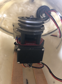
Cabrestante RG y escuadra de soporte.
El proceso
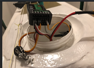
Taladre un agujero en el mamparo delantero en el lado izquierdo para el interruptor de encendido / apagado eléctrico y ajuste.
Coloque el cabrestante en el soporte de soporte y ajuste suelto al mamparo.
Haga un agujero en el soporte cruzado para el servo y coloque y pase el cable a la olla de radio.
Haga un agujero en la parte superior de la olla de radio justo debajo de su marco de soporte y pase el servo y el cable del interruptor de la batería al interior de la olla a través del orificio.
Conecte el servo del timón al canal 1 del receptor.
Conecte el conector del cabrestante al canal 3 y coloque el tercer cable suelto del cabrestante en una clavija central redundante, por ejemplo, el canal 5.
Conecte el interruptor al cabrestante. Utilice conectores XT30 siempre que sea posible o obtendrá suficiente potencia para el cabrestante.
Si enciende la alimentación, con un poco de suerte, un transmisor encendido moverá el timón y el cabrestante.
Hay una sección completa sobre la configuración del transmisor de radio. AQUÍ .
Si todo funciona, está listo para colocar el ajustador de hojas sin fin.
La hoja sin fin es un trabajo complicado. Compré el cabrestante con una polea de retorno autotensante, es decir, está equipado con un resorte que evitará que la línea de la hoja se afloje.
Encuentre los puntos finales del cabrestante moviendo la palanca de control en el transmisor completamente hacia arriba y hacia abajo. Utilizo hacia arriba para la hoja completamente hacia afuera y hacia abajo para completamente adentro.
Dejar la palanca de control hacia abajo (hoja adentro). Tome dos líneas, hágalo pasar por los pasamanos del mamparo y corra hacia el cabrestante. La línea exterior tirará de las hojas hacia adentro y la interior dejará que la hoja salga. En el cabrestante, la polea inferior tiene una hoja hacia adentro, la polea de resorte superior está hacia afuera. Con la línea exterior, ate la polea inferior y envuelva 5 veces la polea. Ate la línea interior a la polea superior, pero solo use una y una medias vueltas. Manteniendo las líneas ligeramente tensadas para que no pierda las vueltas en el cabrestante, ahora puede montar el cabrestante de forma segura.
La línea exterior corre a lo largo de la cubierta y a través de la polea de popa cerca del estay trasero en el lado de estribor, se enrosca hacia adentro y luego se ata a un anillo de acero inoxidable de 5 mm a 2 "del bloque de polea. La línea interior (hoja hacia afuera) se puede tensar, sentirá la resistencia de la polea autotensora y se atará al anillo de acero inoxidable para que el sistema sin fin esté razonablemente apretado. Las hojas principal y del foque se atarán al ring. El sistema de escota de mayor sin fin está completo.


If you turn the power on, with any luck a switched on transmitter will move the rudder and winch.
There is a whole section on the setup of the radio transmitter HERE.
If all works you are ready to fit the endless sheet adjuster.
The endless sheet is a fiddly job. I bought the winch with a self tensioning return pulley, i.e it is fitted with a spring that will stop the sheet line going slack.
Find the end points of the winch by moving the control stick on the transmitter fully up and down. I use up for sheet fully out and down for fully in.
Leave the control stick down (sheet in). Take two lines and thread through the bulkhead fairleads and run to the winch. The outer line will pull the sheets in and the inner will let the sheet out. On the winch the bottom pulley is sheet in, the top sprung pulley is sheet out. With the outer line, tie off on the lower pulley and wrap 5 times round the pulley. Tie the inner line to the upper pulley but only use one and a half turns. Keeping the lines lightly tensioned so you don't lose wraps on the winch, you can now securely mount the winch.
The outer line is run along the deck and through the aft pulley near the backstay on the starboard side, threaded out to in and then tied to a 5mm stainless ring 2" from the pulley block. The inside line (sheet out) can be tensioned, you will feel the resistance of the self tensioning pulley and tie off to the stainless ring so the endless system is reasonable tight. The main and jib sheets will tie off to the ring. The endless mainsheet system is complete.


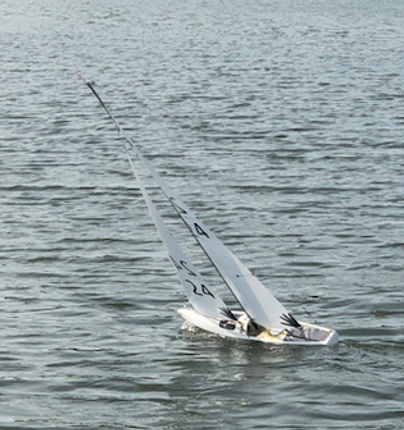
El final resulto
Next Section